Using Software in Qualitative Research
A Step-by-Step Guide
Chapter 13 – Interrogating Data (MAXQDA)
Download the pdf for this chapter guide here.
Chapter 13 discusses interrogation of data that can happen at varied levels and at many moments during analysis. Already in Chapter 6 we referred to Text search tools where the content is explored. Interrogation can also happen in terms of coding work you have previously achieved. You might wish to discover relationships between codes which co-occur in some way in the data or need to compare them across subsets of data (indicated by the application of variables or attributes to data). Types of queries vary from simple to complicated tasks; summarized, charted information where the results are already available in the background is available in some software. See all coloured illustrations (from the book) of software tasks and functions, numbered in chapter order.
Sections included in the chapter:
Incremental and iterative nature of queries
Creating signposts for further queries
Identify patterns and relationships
Qualitative cross tabulations
Quality control, improving interpretive process
Tables and matrices
Charts and graphs
This exercise will demonstrate several of the ways in which the coding query function can be used to interrogate your data. All of these routines are based upon a project which has been coded extensively and consistently, as you will get little of value by running complex coding queries at an early stage in your analysis. These queries allow you to search for patterns and anomalies in the sequences with which particular codes have been applied, and then allow you to re-visit the underlying data so that you can interpret those patterns or anomalies.
A coding query can be started from the menu option “Analysis > Coding Query”, or with an icon on the standard toolbar, or with a double-click in the status bar (at the bottom of the screen) on the 8th section which normally shows “Simple query (OR combination)”, or from the right-click context menu in the grey margin area of the Retrieved Segments window. These all open a substantial dialog window, illustrated at Figure 13.2.1 below.

Figure 13.2.1 – Coding Query Dialog
When you open the coding query dialog you must create a name in the top field, as without that the routine will not generate any results. If you do not want to create a long list of trivial queries as you experiment with this routine you can keep on editing one query as many times as you like, so maybe make your first query name something like “Trial 1” or “Testing”. The program will store your selections in the sections for Weight score, User, Display of results, Kind of view, and Query type when you click on the “Start” button to run this query. However each time that you re-open a query you will have to make the required selections in the sections for Documents and Codes as these will default to “all”.
To create another query and store it, use the drop-down menu in the top field and select the “<new>” entry before renaming it as required. The drop-down menu will then include this as another option in the future. The delete button to the right will remove a stored query altogether, so that it is no longer included in the drop-down list.
Of course for the very simplest queries you do not need to open this dialog. As soon as you activate some documents and one or more codes in the main working screen the program will retrieve the segments that match those activations linked with the default “OR” combination. You only need to open this dialog if you want to add some further requirement to that retrieval as represented by the selections in this dialog.
Experiment with some of the options by changing selections for your test query. If you have some segments with different weights attached, try using those values to restrict the retrievals. If you have applied codes under more than one user name, try using that section to retrieve codings applied by one user then another. Look at the effect of displaying a simple retrieval from several activated documents and several activated codes in the various sequences offered in the 5th section of the dialog. Make sure that you feel comfortable with all of the possible settings offered in this dialog before moving on to the complex queries in the next section.
Complex Coding Queries
The element missing from the selection choices shown in Figure 13.2.1 and the aspect that adds complexity to a query is the possibility of combining multiple codes in different ways. These ways include intersections of 2 codes exactly, or looser overlaps between codes, or even situations where 2 codes occur ‘near’ to each other – and several more types of pattern that you may wish to search for. These combinations are set up in a second dialog window that is opened when you select the radio button beside “complex” at the foot of the Coding Query dialog and click on the “Next” button.

Figure 13.2.2 – Starting a complex coding query
Note how the highlighted button in Figure 13.2.2 changes label depending on the choice of query type. When you select “simple” the button shows “Start”, but when you select “complex” this button changes to “Next” which is an indication that a further dialog box will be opened.
The dialog for the complex part of a coding query is illustrated in Figure 13.2.3 below. The way this works is that you first select a function from the drop-down menu in the field at the top of the dialog. This selection may change the availability and appearance of the other fields in the dialog, as these will reflect the function chosen. You bring the required codes into the sections labelled “A” and “B”, and set other parameters in section “C” as required, and observe the number of segments found to match the function and codes in the blue highlight bar labelled “Segments found:”. When you click on the “Execute” button at the bottom the dialog closes and the segments found are displayed in the Retrieved Segments window in the manner set by the parameters in the previous dialog.
In this illustration we have chosen the function “Intersection (Set)” at the top. A brief explanation of this function is shown at the bottom of the window, and a visual illustration is in the panel to the right. Before opening the query we activated all of the codes in the “Emerging codes” and “Sensitizing Concepts” code groups and these are listed in the “A” section of the dialog. Finally we have set the parameter in the “C” section to the value 2. This set of parameters is asking the program to search for all places where any 2 of the activated codes have been applied to the same data, and it has found 8 such instances (as shown in the “Result” bar). These 8 ‘hits’ will be shown in the Retrieved Segments window when we click on the “Execute” button.

Figure 13.2.3 – Complex coding query
TIP: An explanation of the visual illustration for this function (as shown in the panel to the right) is as follows. Four codes have been activated (1, 2, 3, & 4) in section A. The parameter in section C has been set to value 3 – so only when 3 of the chosen codes intersect is there a hit. The hit shown will only return the segment of data that is coded to all 3 of the intersecting codes.
The range of functions can be seen by using the drop-down menu, and this is illustrated in Figure 13.2.4 below.

Figure 13.2.4 – Complex Query function list
Full details of each of these functions are given in the MAXQDA11 help materials, in the chapter called “Complex Retrievals > Variations of Logical Code Connections” and a brief summary of each is provided at the end of this exercise. However, it is worth pointing out now that when you use the “Intersection” function the program will only record a hit where every one of the codes in Section A has been applied to data segment, so if you activate 5 codes and try this function you are unlikely to get many results as there may be few instances where all 5 codes are applicable to the same text. If you want to find the intersection of any pairs of those 5 codes you should use the “Intersection (Set)” function with the parameter in section C set to 2 (as shown in Figure 13.2.3 above). To experiment with the intersection function just use a pair of codes in the section A box.
Techniques for Complex Queries
There are various techniques for getting the required codes into the section boxes, and these should be practised now. Section A works directly with activated codes, and this is not affected by the settings in the previous dialog (as illustrated in Figure 13.2.1). You can activate more codes in the Code System window while the Complex Query dialog is open, but you will have to click on the “All activated codes” button just above section A to add the newly activated codes to the list shown there. Alternatively you can simply drag another code from the Code System window into this panel and it will be shown there immediately (but it will not be activated by this procedure). A code can be removed from this section by clicking on it to highlight it, and then clicking on the “Remove” button (and this will not change its activation status in the Code System).
Section B works a little differently. It only becomes usable when a function is selected that logically needs a second section. The function “Followed by” needs to have 2 elements so that it reads [find the segments where] a code in Section A is followed by a code in Section B [within a] maximum distance of n paragraphs (and the value of “n” is set in Section C). To get a code to appear in section B you have to select it from the “Quick List” which is opened by clicking on the box with 3 dots that appears at the right of section B when that section is required logically.

Figure 13.2.5 – Using the Quick List in Section B of a Complex Query
The Quick List holds the code names that have been clicked on recently in the Code System window. So, if you cannot see the code that you want to use in section B when you open the Quick List, close it again with the Esc key, click once on the required code in the Code System window, and re-open the Quick List where you should now be able to see it. (You cannot drag a code into section B in the way that you can drag one into section A).
You should be able to see that the number of hits shown in the results bar changes whenever you change any of the parameters in the Complex Query dialog. So you should keep checking this number as you experiment with different functions and settings. When you finally click on the “Execute” button you should find that the Retrieved Segments window then contains that same number of segments, only now you can see the actual data that satisfies your query. By clicking on a segment in the Retrieved Segments window you display it in the Document Browser, and there you can check the coding brackets and confirm that each segment does indeed match the requirements that you set in the query.
Finally, in this part about techniques, you should consider the place of subcodes in complex queries. You may have noticed that there is a button labelled “Subcodes” within the function part of the dialog. This can be used with functions such as “Intersection” to let the header of a group of codes stand-in for the group and then the query will search for each subcode in that group one at a time.
Let us look at this in the focus group documents as a way of thinking about what topics the different speakers have discussed.
- Reset all activations with the button on the standard toolbar (to get a clean start for a new query), and then activate all of the focus group documents, but don’t activate any codes yet
- Open the Coding Query dialog and create a new query called, say, “FG Speakers”, leaving all of the settings in the first query dialog at their defaults
- Click on the “complex” button at the bottom followed by “Next” to open the complex query dialog
- Select the function “Intersection” at the top and click on the “Subcodes” button so that it is highlighted
- Using drag & drop, bring just the header for one of the groups of thematic codes that has been applied to the focus group transcripts into Section A (we will use “Broad-Brush Codes”)
- Again using drag & drop, bring one focus group speaker code into Section A
- Figure 13.2.6 shows the query screen at this stage

Figure 13.2.6 – An intersection query using subcodes
Now, although we know that no data segments have actually been coded to the group header “Broad-Brush Codes” we can see that there are 4 hits. These must be between the specified speaker and some of the subcodes of this group. Clicking on the Execute button brings those hits into the Retrieved Segments window where we find that they amount to “Security” (1), “Debt” (1), and “Concern for younger” (2). Hopefully this demonstrates how the “Subcodes” function works in this query.
In the following descriptions we will concentrate on the way the selected codes and functions interact. In each description it should be understood that the segments of data to be retrieved will also be determined by the activation settings of documents, but that will not be repeated each time.
Intersection
This query function searches for the segments of data that have been coded with all of the codes specified in Section A. If you include 5 codes in Section A this function will search for segments which have been coded to all of those 5 codes together. You are most likely to get positive results if you specify just 2 or 3 codes in Section A.
There is one variation on this description which involves the use of a code group header and its subcodes. By applying the Intersection function with the “Subcodes” button highlighted, if you specify a code group header and one other thematic code, the routine will report all intersections of the thematic code with each of the codes in that group separately.
Intersection (Set)
This query function is more flexible than the previous type of intersection. Here you can specify any number of codes in Section A and then, in Section C, you specify exactly how many of those codes must be present simultaneously for a segment to be selected. So the program will search for segments of data with that number of codes from the specified list all present together. With this function you need to be careful to set a reasonably low figure in Section C (such as 2 or 3) in order to obtain positive hits.
Clearly, you need to think about the methodological justification for searching for combinations of codes that intersect in this way.
Overlapping
The overlapping function works in a very similar way to the first intersection function. The difference is that it reports the whole segment that is coded with either of the codes around the overlap (whereas the intersection function only reports the smaller segment that is coded with both codes). Thus the overlapping function will report the same number of hits for a given selection of codes in Section A as the intersection function would for that particular selection. Once again you will be more likely to obtain positive results if you only specify a small number of codes in Section A.
The Subcodes button works with the overlapping function in exactly the same way as it does with the intersection function.
Only one code
This function reports on all of the data segments that have been coded with just one of the codes listed in Section A. In a sense this is somehow the inverse of the intersection/overlapping functions, as it will exclude all of the hits that would be found by those functions for a given selection of codes in Section A.
A useful application of this function may be found in the analysis of the survey question data, to identify responses which have not yet had any thematic codes applied to them. Activate the Survey data documents only, then add the structural code for one question to Section A and activate all of the thematic codes used for the analysis of that questions responses and add those to Section A. Then apply the function “Only one code”. The resulting hits should be just the responses to which none of the thematic codes have been applied yet, as they will be data with only the structural question code. You can then consider whether any further thematic codes are needed to summarise this data.
Only this code
This function is similar to the previous one but the difference is that you can specify a particular code to be the focus of attention. This function will report all of the segments which have the code specified in Section B and none of the codes specified in Section A intersecting or overlapping with it. Clearly it will be important that you do not include the same code in both Sections A and B or you would create a logic that is impossible to satisfy.
It would be advisable to select the code in Section B first, before specifying the codes for Section A.
If inside
This function searches for data segments which have the code specified in Section A that are within larger segments which have the code specified in Section B. So the code specified at B provides a context within which this function searches for segments with the code specified at A. Note that if the A code extends beyond the boundaries of the B code then there will not be a hit recorded.
This function has an additional set of parameters in the Result section of the dialog box in which you can choose whether the reported segments should be those for the code in Section A, those for the code in Section B, or both.
If outside
This function searches for data segments which have the code specified in Section A without any intersection or overlap with the code specified in Section B. So now the code at B is used as an exclusion device so that we can examine all of the instances of the code at A where the code at B is not present.
There are no additional choices for this function in the Result section, the reported segments will be just those from the Section A code.
Followed by
This function searches for data segments with the code specified in Section A where the code specified in Section B is found within a specified number of paragraphs afterwards. So there are 3 elements required to specify the search, a code for Section A, a code for Section B, and the maximum number of paragraphs that may separate them. With this function you also have the choice whether to report the segments for the Section A code, the Section B code, or both.
Note that this function will include an intersection of the two codes in the same paragraph as a hit, presumably on the logical basis that a gap of zero paragraphs is within a specified range of, say, 2 paragraphs.
Note also that there is no function for “Preceded by”. That effect can be achieved by reversing the specifications of the codes in Sections A and B and still using the “Followed by” function.
Near
This function is similar to the previous one but without specifying a particular sequential order for the two codes to be found. Once again you have to specify a code in Section A and another in Section B and a maximum number of paragraphs by which they may be separated. But this time a hit will be recorded if the A code comes after the B code, and also if the B code comes after the A code, within the given number of paragraphs. As before you can choose whether to report the A codes, the B codes or both for the resulting hits.
This is the ‘loosest’ from of association between codes that you can search for. It probably needs to be used with considerable caution as the presence of two codes near to each other may be merely a coincidence and not necessarily an indication of any connection between them.
Further points to consider with complex queries
Note that your analytical work need not stop with the production of a list of data segments that satisfy the parameters of a particular query function as described above. By using the “Execute” button to extract the data segments and display them in the Retrieved Segments window you can generate a specific subset of your data which can then be used by further functions. For example it may sometimes be informative to run some lexical searches on the hits from a successful complex query, or even a Word Frequency report using MAXDictio, because both of those functions have the facility to restrict their application to “Only retrieved segments”. These could provide some clues to deeper patterns of language within apparently simple commonalities.
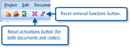
TIP: It is a good idea to reset activations and retrieval functions after running complex queries. It is easy to forget to do this and then you may mislead yourself with an odd result on a later query when some aspects of the earlier one remain active. There are two convenient buttons on the Standard toolbar for this, clicking on these one after the other will ensure that subsequent analysis work has a clean start. These are shown in Figure 13.2.7 below
This exercise will demonstrate several of the ways in which patterns of code frequencies may be examined as a way of finding patterns in the underlying data. Each of the routines discussed below generates a table with coding frequencies as the basis of the cells, however at any stage it is possible to drill down to the underlying data and retrieve all of the segments that make up a particular frequency in the Retrieved Segments window, and then to see them in their original context in the Document Browser window. So, although these routines work at a level of some abstraction, you are never very far from the source data.
The routines described below are:
- Code frequencies
- Statistic of subcodes
- Code Matrix Browser
- Code Relations Browser
- Crosstabs
Code frequencies
You should be familiar by this time with seeing the overall frequency with which each code has been used beside its label in the Code System window. However, you can see much more information about the codes by using the function “Codes > Frequency of codes”. This opens a new window, which is labelled “Code variables”, with two possible views and you can toggle between these views with the 5th icon from the left (“Variable view Ctrl+O”). You may need to change some of the display settings in the alternative view in order to switch on (or off) the display of some details.
If you want to compare the frequencies with which some codes have been used in different documents you can do it in this routine. Clear all activations, then select the routine from the main menu options. Toggle into the table called “List of code variables” and look at the column headed “To be displayed”. Here you can select which elements of data will be shown in the other table view, make sure that there are ticks in the boxes in this column for the rows “7 – All coded segments” and “8 – Activated coded segments”, then toggle into the other table view (labelled “All”). Scroll down this table which lists all of the codes in the Code System until you reach some codes of interest. Scroll sideways if necessary until you can see the columns for “All coded segments” and “Activated coded segments” (these titles may be truncated in the column headers but you can always drag the column margins to display more of the titles). At first the “Activated …” column should be all zeros, but when you start to activate some of the documents in the Document System window (hint – Ctrl+click on a document label there) then you should see the frequencies change in this column.
Note that you can also view some percentage values for individual codes by ticking to display the code variables “13 – all coded segments %” and “14 – Activated coded segments %”. Some of these points are illustrated in Figure 13.3.1 below.

Experiment with re-sorting this table into different sequences by clicking on the column headings. The default sequence is “Code-ID” which is the order in which the codes were originally created in your project.
You can export this table to an Excel spreadsheet or as an html file if you want to send a copy to a colleague outside of MAXQDA11.
Statistic of subcodes
This routine gives you a more sophisticated way of examining patterns of coding frequencies within the structure of a hierarchical group of codes. If you have not used any form of hierarchy in your coding schema you will only be able to use this routine to look at your entire coding system.
Start this routine with the menu option “Codes > Statistic of subcodes” or its icon on the standard toolbar. The first window that opens is used to select the group or groups of subcodes which will be summarised and displayed. You will observe that only the first level of code groups beneath the Code System header is available for analysis in this window.
TIP: If you have used multiple levels in your coding system and you want to analyse one of the deeper subgroups it will not be offered as an available group for this routine at first. But, if you cancel the routine and then in the Code System window temporarily drag the header of the subgroup that you want to analyse onto the Code System header, it will become available for statistical analysis. Afterwards you can drag it back to its correct location in your coding schema.
This window is largely intuitive. You move the code groups that you want to analyse into the right-hand panel by clicking on them in the left-hand panel and then clicking on the right arrow in the central margin. To remove a group from the selection, click on it on the right and then click on the left arrow in the centre. See Figure 13.3.2 below for an illustration. Here we have moved the Survey responses to Q2 up to the highest group level (from being a sub-code group of “Survey responses”) in order to look at its statistics.

There is an additional field at the bottom of this window which might easily be overlooked. The default unit of analysis for these statistics is the number of coded segments, but sometimes you may want to analyse the figures in relation to the number of documents and then you may also exercise a choice between taking the most frequently applied code in each document (“single”) or allowing multiple codes to be recorded for each document (“multiple”). Here we have selected the latter option on the grounds that the survey question being analysed here was similar to a “Tick all that apply” type of question, so multiple answers are to be expected. Often it will be best to leave this section unticked and use the number of coded segments as the unit of analysis.
Now click on the “OK” button to move onto the analysis of the groups you have selected. You will at first be presented with a table view of the first code group in your selection. An example is shown in Figure 13.3.3 below.

Figure 13.3.3 – Frequency table
The first 2 buttons on the toolbar within this window allow you to switch between this tabular view and a chart view of the same data. There are numerous options to customise the chart view for your own requirements and you should explore those. The central part of the toolbar has arrow keys for moving between multiple code groups if you selected more than one group at the first dialog in this routine (we only selected one group so these are greyed-out in this illustration). To the right are buttons for printing and exporting the table or chart.
To continue with our illustration of the survey data subsection of this data set, it is necessary to activate the document group for the survey data before starting the routine. There is then an additional field on the group selection dialog which asks “Only for activated documents” and then the missing data field in the table has a more accurate value for the number of survey respondents who have not provided an analysed response to this question.
Code Matrix Browser
The Code Matrix Browser provides a way of looking for patterns in the codings applied to a range of documents. It generates a table with a column for each document and a row for each code, showing the frequencies with which each code appears in each document as the values in the cells.
You can customise the contents of this table in several ways. You can restrict the range of documents and codes included in the table by using activations before starting the routine. You can use document groups to aggregate the frequencies into fewer columns in the table. You can apply weighting criteria to restrict the coded segments counted.
Start this routine with the menu option “Visual tools > Code Matrix Browser”, or with the short-cut keystroke “Ctrl+B”, or with its icon in the Visual tools toolbar. There is an initial dialog to set some basic parameters for the table, as shown in Figure 13.3.4 below.

It will usually make sense to activate a limited number of documents and codes before you start this routine and limit the table to these items only, otherwise you may be shown a very large table which is difficult to interpret. Here we have activated the focus group transcripts and the main groups of thematic codes applied to them before starting the Code Matrix Browser.
Figure 13.3.5 shows the output table generated with the settings and activations just described. The main body of the table should be quite easy to interpret, but the display can be customised in various ways.

Figure 13.3.5 – Code Matrix Browser
Take some time to explore the icons on the toolbar within this window. The first 3 on the left are all about exporting the table in different formats. The 4th icon is labelled “Quote matrix”, this exports all of the coded segments and displays them in an Excel spreadsheet with the same structure as the table so that, instead of the number 3 for the GP1 document and code “Angry”, you can see all of those 3 segments of text in that cell of the spreadsheet. Use this facility with care because it is easy to create an enormous spreadsheet.
The next 3 icons control the width of the columns in the table as displayed in MAXQDA11, and wider columns are needed to display the full names of the documents concerned. The first of these gives very narrow columns with no name identifiers at all, this may be useful when looking for patterns in the frequencies without knowing which document is which.
The next 5 icons are all concerned with how the frequencies are displayed, whether by numbers or symbols, and how the relative sizes of the symbols are to be calculated. The icon with numbers “123” is the key that toggles between the frequency numbers (as shown here) and the symbols. The next button gives you a choice between circles and squares for the symbols. When you show symbols then you have the choice between calculating their size in proportion to all coded segments or the column or row totals. When the table shows symbols you can see the underlying frequency value by holding the mouse pointer over a symbol and reading the number of coded segments in the temporary tooltip box that opens.
The 13th icon in this toolbar gives you the possibility of recalculating the table with the unit of analysis set to documents rather than coded segments. This means that the decision taken on the preliminary dialog in this respect is not final, you can toggle between the two units of analysis within the table.
TIP: Note that the each code group has a minimise/expand (“-/+”) box to its left. After generating the table you can choose to adjust the display by minimising a group of codes, in which case the values shown on that row will be the aggregate for that whole group. Later, you can expand such a group once more and revert to the detailed frequencies for each code in the group. However you can only aggregate columns on the basis of preselections of groups or sets in the preliminary dialog window.
If you change your mind and want to add more documents or codes to the table you can do this with the help of the 14th icon in the toolbar (labelled “Refresh”). With the Code Matrix Browser table still open, simply activate the additional documents or codes as required in their respective system windows and then click on the “Refresh” button. You will see the parameter dialog again but will probably be able to click “OK” straight away as its settings should be the ones you selected before, and then you will see the expanded table.
Finally, if you have activated quite a large number of documents for this table, so that they cannot all be viewed within the table window comfortably, you can use the MAXQDA11 slider bar at the right-hand end of the toolbar to scroll sideways without losing sight of the code names in the rows.
To “drill down” to the underlying data simply double-click on a number or symbol in the table. The program will change the activations to match that particular combination of document and code, and you will be able to read those segments in the Retrieved Segments window (you may need to move the Code Matrix Browser window if it is partly obscuring that section of your screen). You can then select a different cell and drill down to its coded segments in turn.
TIP: Take care not to use the “Refresh” button when you have been using the drill down facility because the table will be collapsed to the single row and column of your last drill down and you will have to redefine your activations and refresh again to restore the full table once more.
Code Relations Browser
The Code Relations Browser has many similarities with the Code Matrix Browser, but this routine is used to search for patterns amongst the intersections or proximities of codes. This table has codes in both its rows and columns.
Start the routine with the menu option “Visual tools > Code Relations Browser”, or with its shortcut keystroke “Ctrl+O”, or with its icon on the Visual tools toolbar. Once again you will see a preliminary parameter dialog window in which you have to determine the contents of the rows and columns of the table. There is an extra complication this time because you are not able to have different activations of codes for the rows and columns as you cannot change the code activations between those selections. So, if you have activated some codes before you started, you have the options to plot the activated codes against the (same) activated ones, all codes against the activated ones, or all codes against all codes. If you want to plot all codes against the activated ones you can choose whether to have the activated codes as the rows or columns of your table.
You do have an option to restrict the calculations for this table to the coded segments in activated documents only. The documents will not appear in the table as such, but they can be used to determine the subset of your project data which you want to examine with this routine. Initially, it is probably best to use all of your data and so make sure that no documents are activated before you start this routine.

Figure 13.3.6 – Options for the Code Relations Browser
The parameters illustrated in Figure 13.3.6 are an initial recommendation. It is probably easier to manage a table with fewer columns than rows, and you have the facility to minimise groups of codes in rows which is not available for columns.
Figure 13.3.7, below, shows part of an output table where the structural codes for focus group speakers appear in the columns and the thematic codes for the focus group sessions are displayed in the rows. This might facilitate identifying patterns in the contributions from different speakers in the focus groups.

Figure 13.3.7 – Code Relations Browser
There are many similarities between the toolbar options for this routine and the Code Matrix Browser described above. The 3 export choices are the same, but there is no Quotation Matrix button. The 3 column width choices are the same, but there are no buttons to vary the calculation of symbol sizes according to row or column totals. The icon to toggle between number values (as shown here) and symbols is the same, and there is the same button to toggle between circles and squares for the symbols, but between these there is a new button to toggle between overlapping and “Near” and there is also a new “Options” button with which you can define within how many paragraphs counts as “near”.
Once again, you can drill down from any cell in the table to the retrieved segments that relate to those overlaps or proximities by double-clicking on that cell’s value or symbol.
Experiment with this routine by first making sure you can control the rows and columns. Note how, if you have “All” codes in the rows, you can quickly hide many of them by minimising their groups. Work with the sideways scroll bar slider to display different parts of the activated codes in the columns. Then explore switching between values and symbols. Next, try changing the “Near” button and reset the number of paragraphs that defines “near” with the options button, and see how the frequency values are affected by these changes. Finally, explore the output options to see how your table appears in Excel and other formats.
TIP: Make sure that you have a clear distinction in your mind between the Code Matrix Browser (CMB) and the Code Relations Browser (CRB). Their icons in the Visual Tools toolbar are quite similar and their names are quite similar, so they can be confused quite easily.
Crosstabs
In methodological terms, the Crosstabs function is quite different from the frequency tables described above, but it does also produce an output table whose cells represent frequencies of coded segments and which looks quite similar to the browsers described above, and so we have included it in this exercise to help you to compare and contrast it with those other routines.
The Crosstabs routine aggregates groups of documents according to their values for a selected document variable and then shows coding frequencies in rows for each of these variable values in columns. This routine has facilities for displaying various percentage calculations in place of the raw frequency statistics but does not show symbols.
To use crosstabs you need to have a number of documents which have been coded in some consistent way and which have a variable that defines some characteristic of the sources that have provided the data. For this illustration we will use some of the data in the survey section of the Document System of this project. This data is more suitable for this form of analysis than the focus group transcripts used above because it has a much larger sample size and has several variables available to us. We start by activating just the “Survey” group in the document system and the code group which has the themes for one of the survey questions, Q2 – “How have you been personally affected by the financial crisis?”
The Crosstabs function can be started in the following ways: with the menu option “Mixed methods > Crosstabs”, or “Visual tools > Crosstabs”, or with its icon on the Visual tools toolbar. Note that these options are not available unless some codes have already been activated (they are all greyed-out otherwise), so first we must activate the code group for the response themes to the required question.
When you start the Crosstabs function you will have to do some work to select the variable and its values which will be used to create the columns of the table and the first dialog screens are concerned with this aspect. Figure 13.3.8 shows two dialogs together.

Figure 13.3.8 – Choosing variables for a cross tabulation
The main formula screen should be a little bit familiar as we have used one like it in other exercises. If there is anything in the main white box use the “Clear list” button and its following confirmation question to remove it so that you start with a blank formula. Then click on the “New” button near the top of the formula screen (the 2nd one back in Figure 13.3.8) to open the “Variables” dialog on top of it. This lists all of the document variables for the project, both system variables (like “Author” and “Bytes”) and the variables we have created (like “EMP STAT” and “MARITAL”). Our illustration project is quite complicated with different types of data so not all of the user-defined variables have been applied to all of the documents and we have to be careful to select a variable which has been applied to the data we will use – the variable “EMP STAT” is one that was imported with the survey data so we will use that one.
In this dialog you can enter or remove a tick from any of the check boxes beside a variable name with a single click, and we have ticked the required box on the left. We have also clicked a tick into the check box to the right that is labelled “Insert all values into the table” because this saves a bit of work at the next stage. Click “OK” in the “Variables” dialog to close it and return to the Crosstabs formula dialog, where you should now see the list of all the values for the selected variable arranged as a multi-part formula in the main part of the screen. Each row in this list will be a column in the results table, and those columns will appear in the same order as these rows. There should be no need to make any other changes in this example, so now click on the “OK” button of the formulas screen.
There is a dialog question to consider before the calculations are performed – “Only for activated documents?” If you answer “No” here, then the calculations will include all documents which have a valid value for the selected variable, otherwise you can control the data to be used through activations in the usual way.
Figure 13.3.9, below, shows an output for a Crosstabs calculation for the responses to the survey question about how people were personally affected by the financial crisis, analysed according to their employment status, with the results displayed as column percentages.

Figure 13.3.9 – Output for a Crosstabs calculation
You may find it necessary to adjust the column widths (by dragging their margins in the header bar) in order to display enough of the variable labels to interpret them correctly.
The first 4 icons on the toolbar are the same as for the Code Matrix Browser, and have similar effects. Note that this includes a button for a quotation matrix. The 5th icon toggles the table between calculations based on documents and those based on coded segments (for this survey data we consider that the document basis is more valid). The next 4 icons control the display of values and percentages in the table and only one of these may be selected at any one time. You should try each of these in turn and observe how the calculations work.
We have used the column percentages #N because the number of respondents in each category for this variable is highly varied and so it would be difficult to make meaningful comparisons across the categories otherwise. This display shows the number of coded segments in each cell as a percentage of the total number of documents in that column.
A possible interpretation of this table (which is based on only partially analysed data) might include comments that only retired people mentioned their savings, and that the unemployed people mentioned jobs more than any other group while the three groups of people who were working mentioned them in roughly equal proportions, and the retired mentioned them the least. A more surprising element that may be worth more investigation is that the retired people mentioned how their children were affected more than any other group.
You can drill down directly from a Crosstabs table to the underlying data: a double click on the cells in the table will display the relevant segments in the “Retrieved Segments” window.
This exercise outlines two advanced techniques for examining your data that are available in MAXQDA11. These routines use both quantitative and qualitative data and so they can truly be described as using “mixed methods”. They are unlikely to be used in a purely qualitative study.
Typology table
The Typology table works with the document variables that you have brought into or created in your project and performs statistical calculations on them. One variable is selected for the main comparisons, each of its values will be represented by a separate column in the output table. Several other variables may be selected to be shown in the rows of the table, and these are quantified between the values for the column variable. Where a row has a numerical variable the table will show the mean and standard deviation for each cell in that row. Where a row has a categorical variable the table will show the count and percentage for each cell in that row.
This routine becomes part of the mixed methods approach when a thematic code, which has been applied systematically to data in a project, has been converted to a variable. Then that new variable can be used in a typology table to calculate how its values compare across those of another variable such as gender.
Initially we will use the imported quantitative document variables as the basis for a demonstration of how to work this routine, then we will convert some thematic coding to variables and use them in the table.
You start this routine with the menu option “Mixed methods > Typology Table” – there is no shortcut keystroke or toolbar icon for it. The first dialog screen that opens asks you to select the row variables for the table. You can include as many rows as you like, there is no requirement to select all of the possible values for any one variable as you select each row separately, and you can use the documents themselves as rows. Figure 13.5.1 below shows an illustration of the first dialog screen with some of the variables from the survey section of the data already selected.

Figure 13.5.1
When you first see the dialog for selecting the typology table rows use the scroll button to have a good look at the full list of available items. You should be able to see all of the items that are in the Document System for your project as well as all of the possible values for all of the variables that have been set up for those documents and several of the system generated variables. In our example case study we have some variables that have been applied to the survey data and others that have been applied to the newspaper articles. In Figure 13.5.1 we have clicked ticks into all of the check boxes for the values of the variable about the marital status of the survey respondents.
TIP: Because of the length of the list of possible rows in this dialog it would be a good idea to always clear any previous selection by clicking on the button “Deselect all fields” before starting to make positive selections for the current query.
When you have made an initial set of selections, click on the “Continue” button to move to the next screen. This opens the dialog where you select the variable to be used in the columns of the table. This is a 2-stage process which uses techniques we have met in earlier exercises such as the Crosstabs routine. Figure 13.5.2 illustrates this below.
If there is a previous formula in the main window (the one partially hidden in Figure 13.5.2) click on the “Clear list” button at the top to remove it entirely, and then click on the “New” button to start a new formula. This opens the second window (shown in front of the other in Figure 13.5.2). The list of variables in this window is much shorter than the list we saw earlier in Figure 13.5.1, this is because these are just the variable names whereas at the earlier stage we saw a list of all the values for each of these variables. You should select just one of these variables at this stage, and it should be a variable which has been applied to the same documents as the ones you selected at the previous step (otherwise the resulting table will have only zeros) – as we used a survey data variable for the rows, we have ticked the variable about children of the survey respondents.

It will generally be useful to tick the box on the right in this dialog “Insert all values into the table”, as this will create a column for every possible value of the variable you have selected. Then click the “OK” button in this “Variables” window to close it and move back to the formulas section. You should now see several rows of formulas in the main window (we have “[FAM CH]=No”, and “[FAM CH]=Yes” as our formulas because these are the only 2 values of the variable we selected) and each of these will become a column in the final table.
If you did not tick the box for “Insert all values into the table” in the variables window you will have a partial formula line (something like “[FAM CH]= “) which can be completed by using the drop-down menu on the right in the “Value” section of the window. In this way you can create the set of columns one at a time and thus keep control of the sequence in which you want the values of the column variable to be displayed in the final table.
When you have completed the formulas for the table, so that you know you have all of the possible values of the selected column variable represented once, click on the “OK” button once more. This will now generate the results table, and Figure 13.5.3 below illustrates the one we created with the settings described above.

Figure 13.5.3
The contents of the results table will vary depending on whether you have used a numerical or categorical variable for the rows. We have used 4 categorical variable values in our example to indicate the marital status of the survey respondents, and so the typology table has generated counts and column percentages as the cell contents. If you use a numerical variable (such as age) in a row of this table the program will display the mean and standard deviation in each cell of that row.
The toolbar at the top of the window provides several export facilities including Excel, HTML and text file formats, so that you can save a table for inclusion in a report or send it to a colleague.
So far we have used purely quantitative variables that were imported with the survey responses data in this example, and of course these calculations could be done perfectly well in a quantitative program. However, MAXQDA11 includes functions which can convert thematic coding of the qualitative data into document variables, and these could then be used in such a table to examine how the cases that have been analysed with qualitative methods may be interpreted in this quantitative way.
To convert a thematic code to a document variable you use the context menu that opens when you right-click on the code label in the Code System window and select “Transform into a doc-variable”. This routine will create a new document variable with the same name as the code on which you started it, and for each document in the project it will insert into that variable a value equal to the frequency with which that code has been found in that document. You could then use this new variable as a row in a typology table to examine how the distribution of those frequencies falls across the values of one of the other variables applicable to that data.
TIP: Note that this routine does not use activated documents to limit the data on which the calculations are performed. At no stage is there a dialog asking “Only for activated documents”. So these calculations are always performed on the entire project dataset – although where there is no meaningful value for a particular variable that case will simply become a missing value.
Configuration table
A configuration table is a method of examining all of the ways in which several codes arise together in a number of documents. It can handle up to 5 codes in any one table, but there is no restriction on the number of documents involved. The routine looks at every possible combination of the selected codes (each one alone, all pairs, all combinations of 3, etc.) and reports those that are found with calculations of frequency and percentages set out in tables. The basis of the calculations is simply presence or absence of the code in each document; no account is taken of code combinations which arise more than once in the same document.
The routine is started with the menu option “Mixed methods > Configuration table” – there is no shortcut keystroke or toolbar icon for it. The first parameter dialog screen gives you some different ways of selecting the codes to be analysed. You can activate up to 5 codes in the Code System window and then use the button to “Paste activated codes”, or you can use drag & drop techniques to pull up to 5 codes into the dialog. Figure 13.5.4 illustrates this dialog.
You do not have to use all 5 rows in the dialog, the routine works with 3 or 4 codes as well. You can activate codes in the Code System window while this dialog window is open and then use the “Paste” button to add them to the list. Note the check box to limit the data analysed to that in the activated documents only if that is what you want.

Figure 13.5.4
When you have selected the codes and clicked on the “OK” button, two output tables are opened simultaneously in this routine, the summary table and the “Detailed view” table. These are illustrated in a simple example using 4 codes in Figure 13.5.5 below. The two tables appear to be very similar at first but they are showing different information and so it is worth studying them carefully to understand how they work.
In Figure 13.5.5 the summary table is the lower one, while the upper table is called the “Detail view”. The routine was run on 4 codes – “Concern for younger”, “Local facilities”, “Security”, & “Stress”.

Figure 13.5.5
Look at the summary table first. This has a row for each combination of the codes that has been found. It is sorted by the frequency with which each combination has been found. The maximum number of combinations is calculated as 2ⁿ, where n is the number of codes being used, so for the 4 codes there could be up to 16 rows in this table, though as empty rows are not reported there are only 4 showing here. There is a column for each code in the calculation and further columns for frequency and percentage calculations. A blob of colour in any cell of the table indicates which codes were found in combination with the others in that row.
The top row in the summary table of this illustration shows that the codes “Concern …”, “Security” and “Stress” were found together in 2 documents (frequency =2 in this row). The next row tells us that the codes “Concern…”, “Local facilities” and “Security” were found together in just 1 document. The 4th row tells us that all 4 codes were found together in one document. The rows that do not appear tell us that there were no documents with exactly 2 of these 4 codes, and none with only 1 of these codes.
Now turn your attention to the detail view table. This has a row for each document used in the calculations, and a column for each of the codes. Again a blob of colour indicates the presence of that code at least once in that document. Note how the first 2 rows in the detail view have the same pattern of blue blobs; this is showing us which 2 documents made up the frequency of 2 in the first row of the summary table (documents GP1 And GP2 as it happens). There is no significance in the sequence of the rows in both diagrams as each can be resorted separately by clicking on any column header; by default the summary table is in descending order on the frequency column and the detail view is in Document System order.
Now close the two tables and re-run the routine using 4 different codes (and try using the drag & drop technique to bring them into the parameter table). You may need to use the “Delete code(s)” button to remove the previous selection and make room for the next set. You should observe that the summary table always has a total frequency equal to the number of documents being analysed, and the detail view table has this number of rows. This is consistent with the fact that each document has to be assigned to only one of the available combinations of the selected codes, it cannot appear in two places at the same time.
TIP: The Configuration Table is a way of doing case-based analysis of the data. If each document is used for a single case then these tables show how patterns of presence or absence of the selected themes appear in those cases. This may help to identify when certain themes always arise together, or alternatively that others may never be found together. In some situations this may be used to identify that some themes are necessary conditions for others to be found.
Graham Hughes and Stefan Radiker 2014